Posts tonen met het label arduino. Alle posts tonen

vrijdag 10 mei 2013

Maiden flight

Today I finaly got my new x-quad setup with arducopter firmware flying. It still needs some pid tuning, but flying well and feels stable and controllable.


So what's this x-quad configuration all about? The current setup is:
- Razor9Dof IMU  (raw data output firmware over serial port)
- Seeduino Mega 1280 (arduino compatible)
- DIYDrons Arducopter firmware V2.5.3 (with some custom made changes and imu driver)
- 4Channel Analog FM RC controller
- Lantronix B/G wifi module

So I'm flying the x-quad with a standard RC (40mhz fm) controller. The wifi module provides real time telemetry from the quad and sends it to my laptop where I have the DIYDrons APM Planner software running. Next step is to do some PID tuning and try it outside.


*** UPDATE 28 MAI 13

I did some PID tuning and tested the quad outside. Flying manual with rc controller in stabelize mode.


Now we are ready to integrate the sparkfun sup500f gps and test the arducopter gps functions (loiter, rtl, ...) in the mission planner.

vrijdag 15 februari 2013

Arducopter on the bench!

Finaly I got most components working for this project. The arducopter firmware is ported to my seeeduino mega board and is connect to all my other exothic hardware. Now I'm ready to go for some PID tuning on the testbench.

In the movie you can see the these components
- Seeeduino mega 1280 (loaded with arducopter firmware version 2.5.3, with my personal changes)
- Razor 9dof imu (loaded with my own firmware, raw sensor data output)
- Lantronix B/G wifi module
- voltage regulation board to power the wifi module.

The gps is not mounted because I have no signal inside. I currently have only 2 ESC available. These 2 are my spare parts, the other one's are mounted on my Mini-H-Quad. So currently I'm only driving 2 motors. In the video you will see some basics tests, PID tuning will be for next time.


zondag 19 augustus 2012

SkyTraq Sup500f GPS module

First of all, I ported the arducopter v2.5.3 code  to my seeeduino mega board with succes! But because the code that I currently have is not my final release I'll publish it later when everything is finished.

So in this part I will connect my SkyTraq SUP500F Gps module to the seeeduino and see if arducopter works fine. The SUP500F gps module is a product from sparkfun, but at this moment they don't sell it any more:
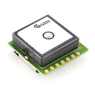

65 Channel SUP500F 10Hz GPS Receiver with Smart Antenna
65 Channel GPS L1 C/A Code
Perform 8 million time-frequency hypothesis testing per second
Open sky hot start 1 sec
Open sky cold start 29 sec
Signal detection better than -161dBm
Multipath detection and suppression
Accuracy 2.5m CEP
Maximum update rate 10Hz
Tracking current ~33mA

Datasheets and software are available on the sparkfun website but also on my google docs page.
So first of all I connected this module to my usb ftdi board (see previous blogs). Then you can launch the gps viewer software and see if it works. After some testing it's time to configure the gps to work with the arducopter code.

You can fully configure the gps module via the gps viewer pc software. If you make sure that the gps module has the default firmware settings you don't have to configure a lot.
- Set the serial baud to 38400
- that's it!

Now you have to configure the arducopter software.
Place "#define GPS_PROTOCOL                    GPS_PROTOCOL_NMEA" in the APM_config.h file. Compile, upload and connect the GPS module to serial 1 on you arduino mega board. It works ! :)

If it should not work or if you would only like to do a simple test, the arducopter GPS library included a simple arduino test sketch. Go to the AP_GPS library folder, locate the NMEA example sketch. Upload and test the GPS.

zondag 12 augustus 2012

Arducopter to Seeeduino Mega

This project isn't finished yet. So what's next?

I'm currently trying to port the ArduCopter uav platform from Diydrones to my hardware. The ArduCopter multirotor uav platform is opensource and arduino compatible. But the guys from DiyDrones build there own hardware boards.
I did choose this road and stop developing my own quadcopter software, because the arducopter project is open source, has a lot of features and has a very nice pc software (ground station). I think porting this project to my own hardware will take less time the continue with programming my own software.

The arducopter firmware I'll try to port is version 2.5.3. After succes I can maybe take a look at v2.6 or 2.7 But the arducopter requirements say that as from version 2.7 there own, but older APM1 board isn't supported anymore. The APM1 board has an atmega 1280 like my seeeduinomega board. The port that I"m going to do is optimezed for the 1280 chip and not the newer 2560 chip that is shipped with the APM2 board.

A second problem is that the APM1 as well as the APM2 board from diydrones have a extra chip that handles RC input. The data that is recieved from your own RC reciever/transmitter will be read and handled by this second chip. It is clear that on a arduino mega board or on a seeeduino mega board there is only one chip. So for this project I will not be able to fly with a normal RC transmitter. But that is not a problem, because the arducopter PC software can handle joystick input to fly any multicopter. And that is what I already did with my own software :)

in the next blogs I'll give more information and try to give a step by step tutorial.

- first of all you have to download the arducopter firmware
http://code.google.com/p/arducopter/downloads/list

- you need to place all the libraries in you arduino program. Go to the folder where you installed arduino. Locate the libraries folder and copy all arducopter libraries to this folder.

- as from know your arduino pc software is ready to compile the arducopter platform. I'm using arduino v0.22 and v1.0. But note that we still have to make some changes in the firmware itself.


dinsdag 24 juli 2012

First flight

My project is progressing very slowly. But here it is. Proof of concept. My multicopter can fly.


As you can see, it still needs some PID tuning. And I really need to learn how to fly and land this thing. I got the impression that there is some latency on my control input/uplink. The copter responds to my controls but I feel that I don't really have it under control.

Equipment quadcopter:
- Alu Quad + frame 60cm square tube 15x15x1.5mm (~ 53cm from motor center to oposit motor center)
- 4 x Motors AX-2210N 1000kv from hobbyking
- 4 x EPP 1045 props from lipoly (2xcw &  2xccw)
- 4 x Blueseries ECS 12 amp from hobbyking
- 4 x homemade vibration reduction motor mount (see previous blog)
- Seeeduino Mega v1.1 board (arduino compatible)
- Razor 9DOF IMU from sparkfun
- LantroniX Matchport wifi module
- Turnigy 3000mAh 3S 20C Lipo Pack from hobbyking 

total weight: ~ 1200 grams

Equipment groundstation:
- wifi router
- laptop
- usb gamepad


The Seeeduino Mega board has my own custom code (written in arduino).  Ok, I did not reinvent fire. I read a lot on the internet. I took the basics and made my own program that controls the quad. The 9DOF imu is equiped with a modified version of the AHRS firmware. Note that it is not the version I upload in one of my previous blogposts. The version I currently use will be uploaded later.

The lantronix B/G wifi module translates wireless ip based UDP/TCP packets to serial uart. I can send commands from my laptop via UDP to the quad copter. The usb gamepad is used to control/fly the quadcopter. The copter sends its data from sensors/batt status/motorspeed/... via the wifi module in realtime back to my laptop. The program on the laptop that controls all this is written in VB.Net (2003)

donderdag 24 november 2011

Mainboard

The Seeeduino Mega will be my choice as main controller. This board is 100% arduino platform compatible. So it's very easy to develop, program and test. The advantage above the original arduino mega is that the Seeeduino Mega is a bit smaller.

Weight: 25.3 grams
ATmega 1280 @ 16MHz
Selectable 5V/3.3V operation
70 Digital IO
16 Analog inputs
14 PWM outputs
4 Hardware serial ports (UART)
More info about the Seeeduino Mega

This litle mainboard will be the central control unit of the quadrocopter. All input sensors and all output control units will be attached to this board.